


Application Guide · Combiblock Series
Combiblock for CSD and Sparkling Water — Isobaric Filling in One Block
Counter-pressure filling, CO₂ return, controlled snift — and the scope items first-time CSD buyers forget.
12,000–36,000
BPH, 0.2–2 L
CO₂
Gas returned, not vented
444+
Lines delivered
71+
Countries exported
ISO/CE
Certified · SGS audited
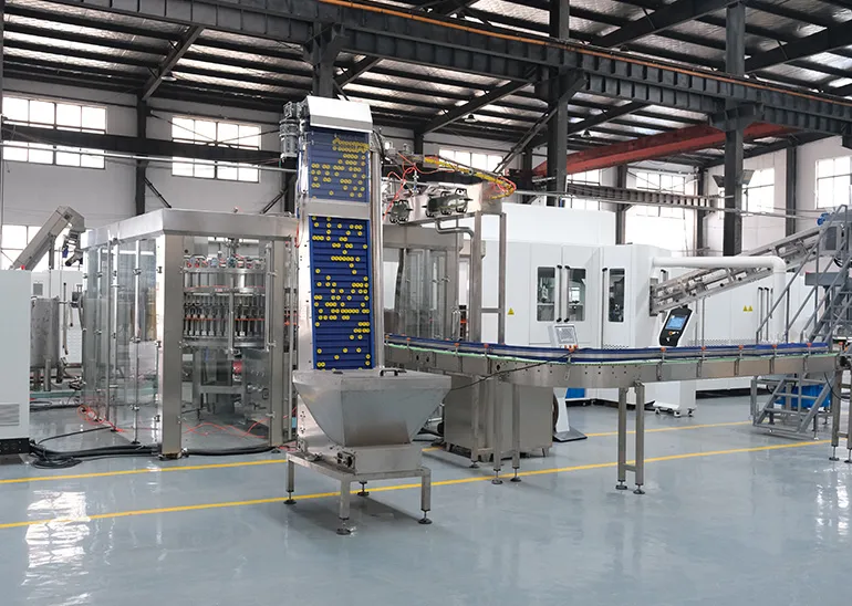
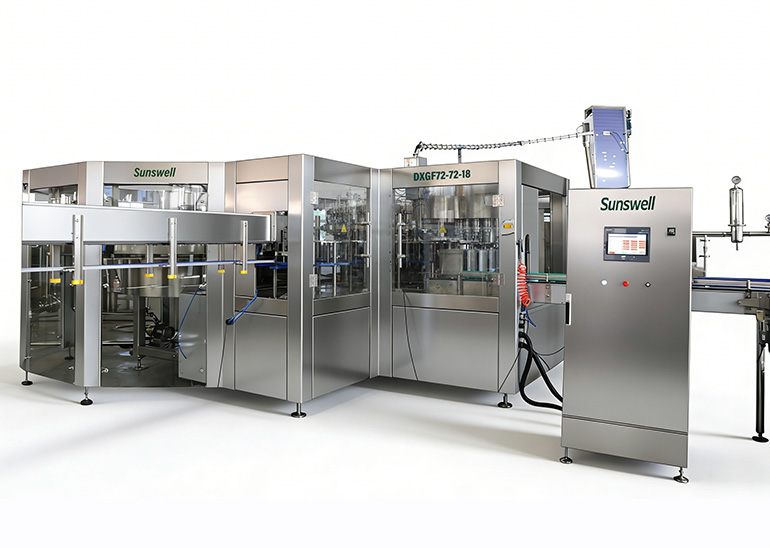
Short answer: A CSD combiblock blows, fills and caps carbonated product in one machine using an isobaric filler: CO₂ pre-pressurises the bottle to tank pressure, liquid enters under gravity with no pressure drop, displaced gas returns to the tank, and headspace pressure is released in a controlled snift before capping. Sunswell supplies CSD combiblocks at 12,000–36,000 BPH for 0.2–2 L in mechanical and semi-electric isobaric versions.
🎯 Key takeaways
- Isobaric filling removes the cause of foaming, rather than managing it — no pressure drop, no gas release
- Displaced CO₂ returns to the tank instead of venting, so gas is not wasted
- 12,000–36,000 BPH for 0.2–2 L; carbonated output is inherently lower than still water
- Chilling, carbonation, CO₂ supply, CIP and a syrup room are needed beyond the filler — the syrup room is the most forgotten
- Mechanical vs semi-electric isobaric is a control and changeover decision, not a carbonation capability one
- Snift timing is tuned on real product — water testing cannot set it, so budget commissioning time
On this page
1. The problem carbonation creates
Dissolved CO₂ wants to leave the liquid. Every pressure drop, every temperature rise and every turbulent surface gives it an opportunity. A filling machine designed for still water opens a valve and lets liquid fall into an atmospheric-pressure bottle, which is precisely the condition that makes carbonated product foam out of the neck.
Three consequences follow, and they are all commercial rather than technical:
- Product loss. Foam that overflows is product you paid for and now have to clean up.
- Carbonation loss. Gas that escapes during filling is not in the bottle the consumer opens, and the drink tastes flat.
- Speed loss. Foaming forces slower filling, so a line rated for a certain output never reaches it.
Isobaric filling removes the cause rather than managing the symptom.
2. How isobaric counter-pressure filling works
- Sealing. The bottle is raised and sealed against the filling valve, forming a closed system with the product tank.
- Counter-pressurisation. CO₂ from the tank headspace flows into the bottle until bottle pressure equals tank pressure.
- Filling. With no pressure differential, the liquid valve opens and product flows in under gravity. Displaced CO₂ returns to the tank through a return path — it is not vented and not wasted.
- Level determination. Filling stops when the product reaches the set level or measured quantity, depending on valve type.
- Snift. Pressure in the bottle headspace is released in a controlled way before the bottle leaves the valve, so it does not foam when it reaches atmosphere.
- Transfer to capping. The bottle moves to the capper on a neck-handling starwheel and is sealed immediately, minimising the time it stands open.
The snift step is where quality is won or lost. Releasing headspace pressure too quickly makes the product foam in the bottle and forces a slower line. Snift timing is tuned during commissioning with your actual product at your actual temperature — it cannot be set correctly on water.
3. What the combiblock adds
Isobaric filling is available on any modern CSD filler. Putting it inside a blow-fill-cap block adds three things specific to carbonated production:
3.1 No air conveyor, no bottle handling damage
CSD bottles have petaloid bases and are blown to withstand internal pressure. Handling them on an air conveyor between machines adds scuffing and base stress that a neck-handled transfer avoids entirely.
3.2 Shorter time between blowing and filling
Freshly blown PET continues to stabilise dimensionally for a period after leaving the mould. A block fills within seconds of blowing, on a consistent and repeatable interval, rather than after a variable journey across the plant.
3.3 One control system for a pressurised process
The filler carousel is a pressure vessel with CO₂ management, and it shares drive and control with the blower and the capper. Timing between filling and capping is mechanical rather than electrically synchronised across separate machines — and on carbonated product the interval between fill and seal directly affects retained carbonation.
4. Capacity and format range
| Product | Bottle size | Capacity range |
|---|---|---|
| CSD and sparkling water | 0.2 – 2 L | 12,000 – 36,000 BPH |
| CSD, larger formats | 2 – 3 L | Quoted on bottle design |
| Still water on the same block | 0.2 – 2 L | Up to 48,000 BPH |
Carbonated output is lower than still water output on comparable equipment, and that is inherent rather than a limitation of any particular machine: counter-pressurisation and snift both take time in the fill cycle. Final capacity is confirmed after bottle drawings, target CO₂ volumes and product temperature are reviewed. The selection method across the range is in combiblock capacity selection.
5. What a CSD line needs that a water line does not
| Requirement | Why | Scope note |
|---|---|---|
| Product chilling | CO₂ solubility rises as temperature falls | Chiller and insulated product piping, usually separate scope |
| Carbonation unit | Dissolves CO₂ into product to target volumes | Carbonator sized to line output |
| CO₂ supply and control | Counter-pressure and gas return depend on stable supply | Bulk CO₂ tank or cylinder bank plus regulation |
| Pressure-rated carousel | The filler bowl operates under pressure | Part of the isobaric filler, not an option |
| Petaloid bottle base | Withstands internal pressure | Affects preform and mould design |
| CIP system | Sugar-bearing product requires cleaning discipline | Specify with the line, not later |
| Syrup room | Blending concentrate, sugar and water to recipe | Usually a separate scope; confirm who supplies it |
The syrup room is the most frequently forgotten scope item on a first CSD project. Buyers price the filler carefully and discover afterwards that blending, sugar dissolving and syrup storage are not in anyone's quotation. Ask explicitly, in writing, on every quotation you compare.
6. Mechanical or semi-electric isobaric
| Mechanical isobaric | Semi-electric isobaric | |
|---|---|---|
| Fill control | Mechanical level determination | Electronic valve control |
| Repeatability | Good | Better |
| Size changeover | Mechanical adjustment | Partly recipe-driven |
| Relative capex | Lower | Higher |
| Maintenance skill | Mechanical fitter | Fitter plus basic electronics |
| Typical choice | Single format, cost-focused projects | Multiple formats, tighter fill control |
Both are genuine isobaric fillers. The difference is control sophistication and changeover convenience, not carbonation capability. A plant running one bottle size continuously often has no reason to pay for the electronic version; a plant running four sizes will recover the difference in changeover time. Full valve comparison across all products in filling valve types compared.
7. Symptoms and what usually causes them
Carbonated lines produce a small set of recurring complaints, and the cause is rarely where the symptom appears. Working through them in the right order saves days.
| Symptom | Most common cause | Check first |
|---|---|---|
| Foaming at the filling valve | Product temperature too high | Temperature at the filler bowl, not at the tank |
| Foaming after the valve, before capping | Snift released too fast | Snift timing and cam profile |
| Flat product at the consumer | Long interval between fill and seal | Fill-to-cap timing and capper phasing |
| Fill level scatter | Unstable counter-pressure | CO₂ supply pressure during full production, not at idle |
| Bottle base deformation | Base design or blowing profile | Petaloid geometry and heating profile |
| Leaking closures | Capping torque or cap batch | Torque sample, then compare cap batch to the FAT batch |
| Output below rating | Filling slowed to control foaming | Chilling capacity at full line speed |
7.1 Temperature is the first suspect
More than half of CSD filling complaints trace back to product temperature at the filler. Chilling capacity that is adequate at start-up can fall behind once the line runs at full output for several hours, and the drift is gradual enough that nobody notices until fill quality degrades. Measure at the filler bowl during sustained production, and size the chiller for that condition rather than for the first hour.
7.2 CO₂ supply is the second
Counter-pressure depends on stable CO₂ supply. A cylinder bank that holds pressure during trials can sag when the line runs continuously, and every fill cycle is affected. Check supply pressure under full production load before adjusting anything on the filler.
Resist the urge to adjust the machine first. On carbonated lines, the filler is usually reporting a problem elsewhere — temperature, gas supply, or closures. Adjusting valve timing to compensate for warm product hides the cause and costs you line speed permanently.
8. What to expect during commissioning
Carbonated lines take longer to commission than water lines, and the extra time is spent on product behaviour rather than on machinery. Water testing verifies mechanics; only the real product reveals how it foams.
- Temperature stability first. If product temperature drifts, nothing downstream can be tuned reliably. Fix the chilling before tuning the filler.
- Counter-pressure setting. Adjusted against actual CO₂ volumes and product temperature.
- Snift timing. The most iterative part of the process, and the one that most affects achievable speed.
- Fill-to-cap interval. Verified so bottles are sealed promptly after filling.
- Speed ramp. Output stepped up while foaming and fill level scatter are watched at each step.
Budget for this in the project schedule. A CSD line that reaches rated output on the first day of product running is unusual; one that reaches it within the commissioning window is normal. The full sequence is in shipping, installation and commissioning.
Frequently asked questions
Can a combiblock really fill carbonated drinks?
Yes, with an isobaric filler carousel. CO₂ pre-pressurises the bottle to tank pressure before the liquid valve opens, so the product enters without a pressure drop. Displaced CO₂ returns to the tank instead of venting. Sunswell supplies CSD combiblocks from 12,000 to 36,000 BPH in 0.2–2 L.
What is isobaric filling?
Filling at equal pressure. The bottle is sealed against the valve and pressurised with CO₂ until it matches the product tank. With no pressure difference, liquid flows in under gravity without releasing dissolved gas — which is what causes foaming and carbonation loss.
What CO₂ level can you fill?
Standard soft drink and sparkling water carbonation levels are handled routinely. State your target CO₂ volumes at quotation stage, because higher carbonation needs lower product temperature, higher counter-pressure and affects achievable line speed.
Why does carbonated product need to be chilled?
CO₂ solubility rises as temperature falls. Filling cold keeps the gas in solution during the fill and reduces foaming. Warmer product needs higher counter-pressure and slower filling to achieve the same result.
Do carbonated bottles need a different design?
Yes. CSD bottles use a petaloid base to withstand internal pressure, and the base design affects both blowing and stability on conveyors. Preform and mould design are agreed together with the machine specification, not afterwards.
Which valve type for CSD?
Isobaric valves are supplied in mechanical and semi-electric versions. Mechanical is the lower-cost option with proven simplicity; semi-electric offers better repeatability and easier size changeover. Both are counter-pressure — the choice is about control level, not about carbonation capability.
Can one line run both still water and CSD?
An isobaric filler can run still product, but a still-water filler cannot run carbonated product. If both are planned, specify the isobaric configuration from the start — adding carbonation capability to an installed still filler is not a practical retrofit.
About the author
Written by the Sunswell engineering team — led by Howie SUN, Founder & CEO, with 14 years in filling and blow-moulding equipment R&D and turnkey project delivery across 71+ countries.
Last reviewed: 2026-08-06 · Reviewed by Sunswell engineering team
Ask our engineering team →Recommend Products
Project references
-

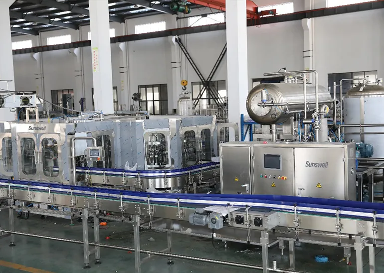
Vizit, 12,000BPH 1L Bottling Line with Combiblock for CSD, Kazakhstan
Country: Kazakhstan
Product: PET Bottled Carbonated Soft Drinks
Capacity: 12000BPH (1L)
Solution:Carbonated Drinks Production Line
Read More + -
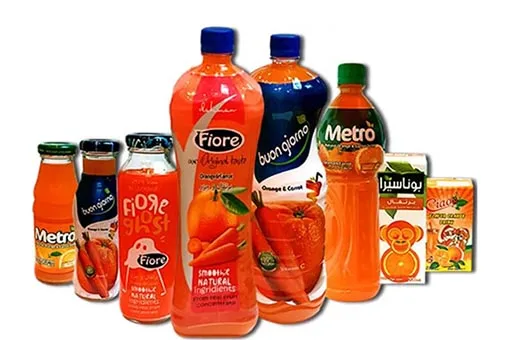
Dahman, 24,000CPH Canning Line for CSD, Syria
Country: Syria
Product: Aluminum Canned Carbonated Soft Drinks
Capacity: 24000CPH (250ml)
Solution:Carbonated Drinks Production Line
Read More + -
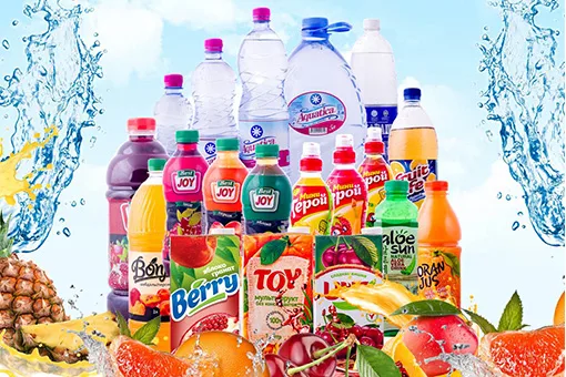
Rauan, 8 Sets of Bottlingand Canning Lines from 12,000-24,000BPH for Water, CSD and Juice, Kazakhstan
Country:Kazakhstan
Product: PET Bottled Sparkling Water, Canned Soft Drink, Canned Tea
Capacity: 25000CPH (250ml)
Solution:Three Lines,7000BPH(1.5L), 15000CPH(330ml),15000CPH(450ml)
Read More +
Have a specific project in mind?
Tell us product, target BPH, bottle sizes and market. We reply with a draft layout, equipment list and lead time estimate.
Fill the inquiry form ↑