

| Combines | Blow moulding, filling and capping in one block |
| Capacity range | 2,000-48,000 BPH |
| Bottle range | 0.2-16 L PET |
| Products | Still water, CSD, juice, tea, edible oil |
| Valves | Load cell, volumetric, mechanical or semi-electric |
| Operation | One operator for the complete block |
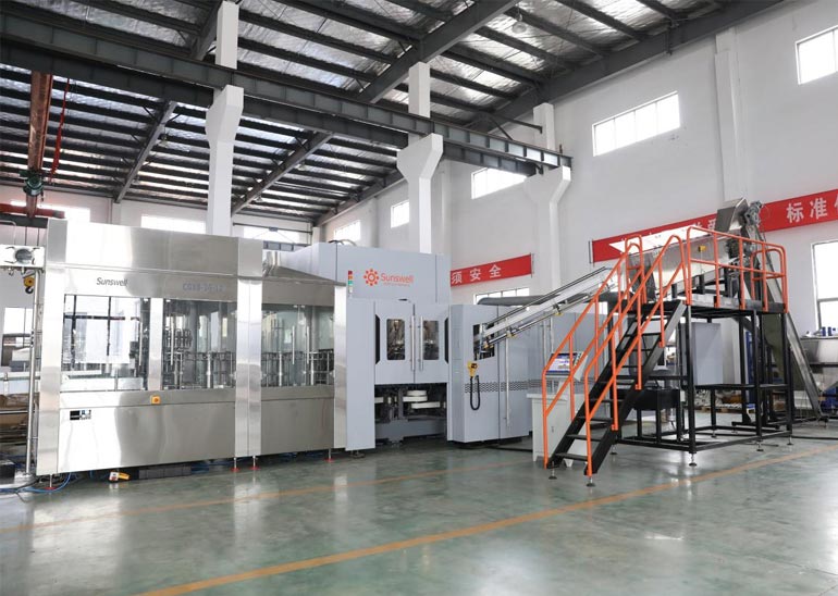
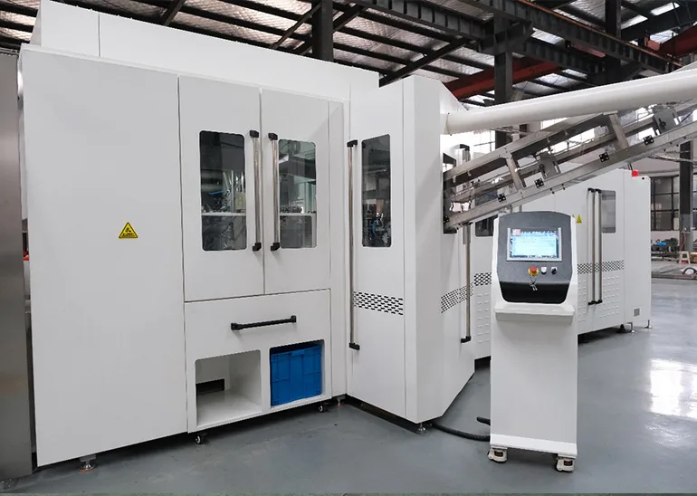
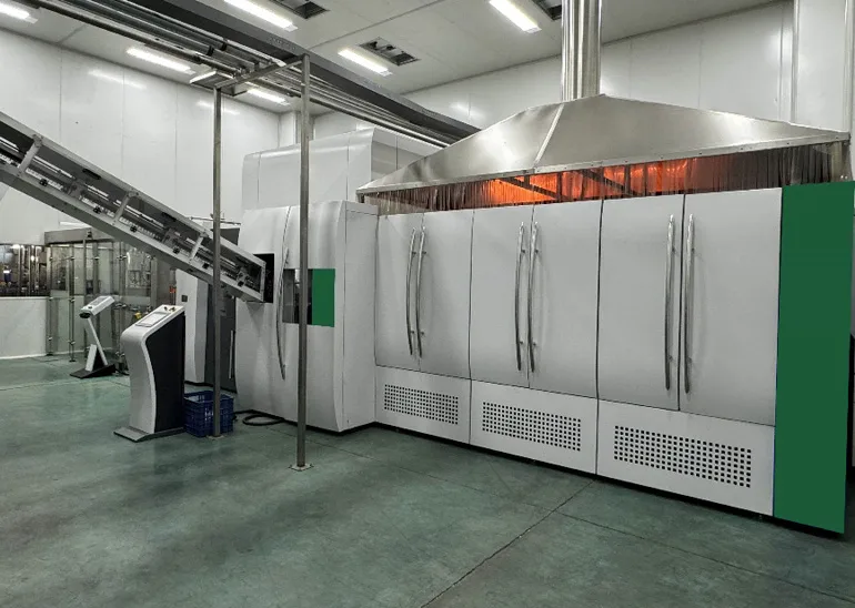
A combiblock joins blow moulding, filling and capping into one frame with one drive and one control system. The preform goes in at one end and the capped bottle comes out at the other, with no intermediate buffer and no bottle storage between blowing and filling.
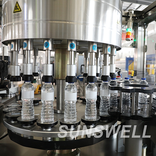
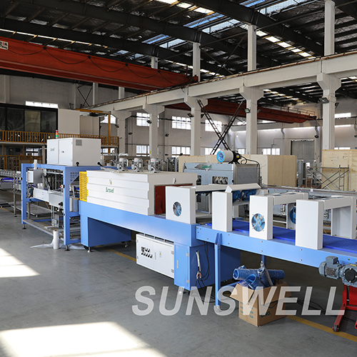
This line is a 20,000BPH 500ML water line, and the main machines include the combiblock with solenoid valve and servo stretching, ROPP labeling machine, film wrapping machine, palletizer, etc.
A conventional line stores empty bottles between the blower and the filler, and that buffer is floor space, conveyor, and a place where bottles collect dust. A combiblock removes all three, and because the three machines share one control system, one operator can run the block. The saving is in the building, not in the machine price.
| Configuration | What is inside | Typical use |
|---|---|---|
| 3-in-1 monoblock | Rinse, fill, cap | Still water in bought bottles |
| Combiblock | Blow, fill, cap | PET lines with in-house blowing |
| Combiblock + labeller | Blow, fill, cap, label | Single-footprint PET line |
| Combiblock + packer | Blow to case | High-volume single-format plant |
The unit behind this configuration is the Blow-fill-cap Combibloc for Still Water.
Because there is no buffer, a stop at the blower reaches the filler in seconds. That is the trade: less floor space and less labour in exchange for less tolerance of short stops. The maintenance plan has to treat the blower and the filler as one unit, with one set of uptime targets.
Throughput and change-part lists are on the Still Water 5L Volumetric page rather than in this note.
The valve follows the product, not the block. Still water runs gravity or volumetric; oil runs load cell; CSD runs isobaric; juice runs hot fill or volumetric. The block is the frame, and the valve set is specified per product family, which is why one combiblock cannot simply switch between water and CSD.
The same question is worked through from another angle in How Blow-Fill-Cap Machines Reduce Labor Costs.
With change parts for the mould, the star wheels and the filling recipe, yes. The changeover is longer than on a filler alone because the mould set changes, and the production factor for a two-format week is lower than for a single format.
It is designed for one operator on the complete block, which is fewer people than three separate machines need. The saving is real only if the plant also removes the buffer and the bottle handling between stations.
The blower and the filler are mechanically linked, so bottles move directly from the mould to the filler. Removing the buffer saves space and dust exposure, but it also removes the cushion that absorbs short stops.
Through a CIP circuit that covers the filler and the product path; the blowing side is cleaned separately as a dry section. The two cleaning regimes run on different schedules and should not be merged in the plan.



Country: Kazakhstan
Product: PET Bottled Carbonated Soft Drinks
Capacity: 12000BPH (1L)
Solution:Carbonated Drinks Production Line
Country: Maldives
Product: PET Bottled Mineralized Water
Capacity: 24,000BPH (500ml); 2 Lines
Solution:Water Production Line



 +86 13921964455
 [email protected]

A2 Dongjiu Industrial Park, 30 East Jintang Road, Tangshi, Zhangjiagang, Jiangsu 215600, China


